Recent Posts

Blogroll

                                          My PIC12F683 Development Board
Office Map Circuit diagram for each experiment may not be available separately because they are conducted with PIC12F683 development board that I made. So, the readers should first see the schematic of my development board.

Saturday, February 13, 2010

Experiment No. 1: 3-bit LED Up Counter

This is the first and the simplest project we are going to test on our PIC12F683 experiment board. We are going to make a 3-bit up counter that counts from 0 to 7. After 7, we are going to reset it to 0 and then start again, and so on. The 3-bit counter output will be displayed on 3-LEDs on the board. There will be a 1s delay between each up count.
Setup:
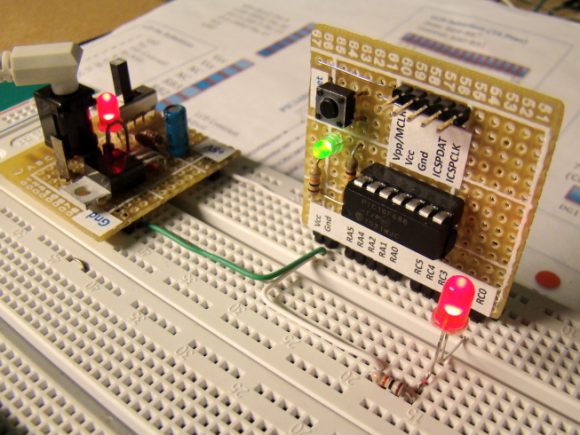
Connect GP0, GP1, and GP2 (pins 7, 6, and 5 of PIC12F683) to LEDs 3, 2, and 1 respectively.
 
Connect GPIO2, 1, 0 pins to LEDs 1, 2, 3 using jumper wires.


Software:

/*
  PIC12F683 Experiment Board
  Experimen No. 1 : 3-bit Up Counter
  "LEDs 1, 2, and 3 are connected to GPIO2, GPIO1, and GPIO0
   respectively"
*/

short i;
void main() {
CMCON0 = 7;
TRISIO = 8;  // GPIO0-GPIO2 are Outputs
ANSEL = 0;
GPIO = 0;
delay_ms(500);
i=0;
do {
   GPIO=i;
   delay_ms(1000);
   i = i+1;
   if(i == 8) i=0;

   }while(1);
}

Output:
3 LEDs count up to 7, then reset and count starts again.

0 comments:

Post a Comment

Online Embedded Systems Lab

This online laboratory teaches you the fundamentals of microcontroller-based embedded system development through a series of laboratory exercises. Most of the time, students and hobbyists could not afford expensive development kits and software to learn these things. These tutorials are prepared such that you will be building microcontroller projects at a minimum cost. Check this out